
The ESP8266 SoC (System on Crystal) from the Chinese manufacturer Espressif provides the ability to easily develop programmable modules with access to WLAN. The ESP8266 does not have an internal Flash program memory, but uses an external QSPI Flash chip instead.
The ESP8266 main features :
- RISC CPU Tensilica L106 with a clock speed up to 160 MHz
- External Flash program memory up to 128 Mbit
- External quartz with frequency from 24 MHz to 52 MHz
- Built-in high-frequency 2.4 GHz transceiver with IEEE802.11 b/g/n support
- Built-in TCP/IP protocol stack and full support for 802.11b /g/n WLAN MAC
- Peripheral interfaces GPIO, SDIO, SPI, HSPI, I2C, I2S, UART, PWM, IRDA, ADC are available for programming
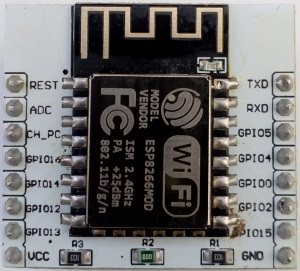
Based on the ESP8266, the Chinese industry produces a large number of inexpensive WiFi modules. For my experiments, I bought two such modules at different times: ESP-12F and ESP-14.
Both modules are shown in the following picture.

The differences between the modules are mainly in the size of the Flash program memory. There is the built-in STM8 microcontroller in the ESP-14 as well.
The STM8 microcontroller has been added to communicate with the ESP8266 module by transmitting AT commands.
Perhaps, the idea was not very successful. This module has been withdrawn from production. That’s why there is no any documentation for the ESP-14 module on the manufacturer’s website.
Both modules are located on a 24 x 16 (mm) PCB with an antenna. All module components are protected by a metal shield.
The pin step is 2 mm, the total contact quantity is 22, the contact location is different on both modules.
UART is used to upgrade the ESP8266 firmware, the programming mode is activated by setting a low logic level on the GPIO0 pin.
I soldered both modules to the adapter boards.
The connection to the computer is made by a USB-UART adapter based on the CP2102 or another chip.
The ESP12F minimum serial wiring is shown in the following picture :

There are also a large number of ECP8266-based modules with a built-in USB-UART converter, which do not require the user to work with a soldering iron. They are ready to work immediately after turning on.
Let’s consider the ESP8266 capabilities using the ESP-12F module as an example. The following information is also relevant for other ESP8266-based modules.
There are several ways to work with the module, the simplest one that does not require changing the
firmware is to use text AT commands
Two Espressif SDKs are available for ESP8266 programming.
ESP8266 can also be programmed in the Arduino IDE.
Programming ESP8266 using Arduino IDE
You can download the Arduino IDE from the official Arduino website.The Arduino integrated development environment is very simple and cross-platform. The source file with a C++ program is called a sketch in the Arduino IDE. This is the main program module from which numerous library functions can be called (or objects created on the basis of library classes).By the way you can create lots of source files in your sketch directory.
Guess what the functions setup() and loop() do according to their names.
setup() is needed to execute initial initialization. There is the main program thread in the loop() function.
By default, the program for Arduino is single-thread, the program code is executed within an infinite loop, but it is also possible to use the FreeRTOS task scheduler. To do this, you must use the FreeRTOS library.
There was no FreeRTOS support for ESP8266 in Arduino libraries at the time of writing.
Although the manufacturer Espressif has already ported FreeRTOS to ESP8266 in its RTOS-SDK.
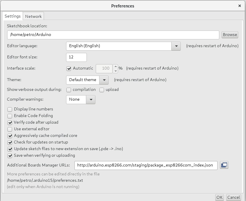
Use the link http://arduino.esp8266.com/stable/package_esp8266com_index.json to download the stable library version or http://arduino.esp8266.com/staging/package_esp8266com_index.json for the developer’s version.
You should fill the ‘Additional Boards Managet URLs’ field in the menu item File -> Preferences with one of the mentioned above links.

Another way to add ESP8266 support to the Arduino IDE is to clone the git repository.
This method is described in detail on the following website
$ cd hardware

$ mkdir esp8266com && cd esp8266com

$ git clone https://github.com/esp8266/Arduino.git esp8266

$ cd esp8266

$ git submodule update --init
You can also install binary tools for programming ESP8266, this requires the presence of installed Python 3.
$ cd esp8266/tools

$ python3 get.py
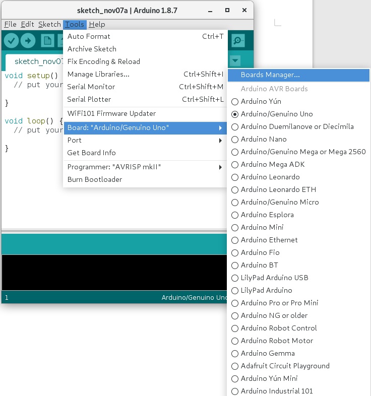
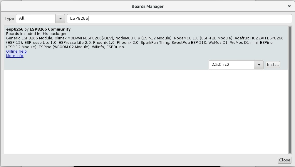
Next you need to select Generic ESP8266 Module in the Tools-> Board menu.
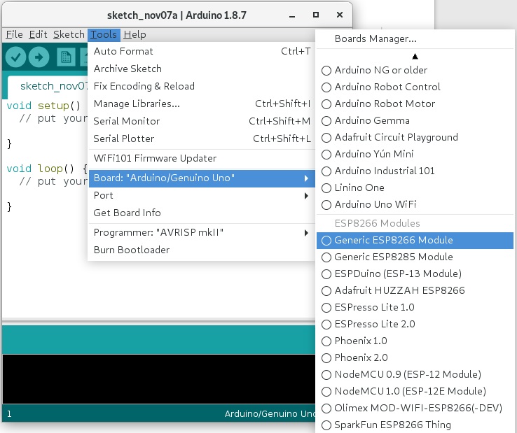
The settings of the ESP-12F module for me look like this:

You can select an interesting example for ESP8266 programming.
Use the File->Examples menu to open Examples for Generic ESP8266 Module section.
Compiling and uploading the firmware to the board is done by clicking the Upload button in the Arduino top menu. The board must be connected to the USB-UART adapter, GPIO0 = 0. The correct COM port number must also be selected in the Tools-> Port menu.
If you are running a Linux operating system, you must allow access to the COM port device, for example, add yourself to the ‘dialout’ group to have access to the /dev/ttyUSB0 file :
$ sudo usermod -a -G dialout

$ sudo systemctl restart
You can call ESP API functions from the Arduino IDE. To test this possibility, open the example File-> Examples-> ESP8266-> TestEspApi.
In this example, I changed the UART baud rate from 74880 to 9600, otherwise garbage was displayed on the screen.

The ESP API description can be found in the ESP8266 Non-OS SDK API Reference documentation.
Documentation for programming ESP8266 with Arduino IDE can be downloaded at this link Welcome to ESP8266 Arduino Core’s documentation!
The examples also have the firmware update over the air OTA(Over The Air).
To test this feature, open the example File-> Examples-> ArduinoOTA-> BasicOTA.
In the example, you need to substitute the name of your wireless network and the access code to it:
|
1 2 |
const char* ssid = ".........."; const char* password = ".........."; |
Download this example in the usual way (via COM port), then open the terminal Tools-> Serial Monitor, disconnect the power supply, GPIO0 = 1, turn on the power again.
The IP address to upgrade the module using OTA will appear in the terminal.
You can flash the module over the air in various ways, including the Arduino IDE, to do this you need to restart the development environment and select the menu Tools->Port wireless device (I have it called esp8266-ab3eff at 192.168.0.107) in the Network ports section.

Then click on the Upload button, there is no need to connect GPIO0 to the ground. The module will be reflashed in the air. But keep in mind that if the sketch uploaded to the module does not support OTA, then the next time you have to reflash the module via UART.
I want to note that programming ESP6266 in Arduino IDE is the easiest way to work with the module.
If you are not satisfied with the capabilities of the Arduino IDE, you can use the PlatformIO framework and program the module based on ESP8266 in your favorite code editor or IDE (such as Eclipse).
Programming ESP8266 in Eclipse using PlatformIO
The PlatformIO framework for developing IoT applications (Internet of things) is written in the Python programming language and allows you to work with Arduino and ARM mbed frameworks, development tools for STM32, ESP8266, ESP32 and many others using various code editors and IDEs. PlatformIO currently supports 923 different debug boards.
PlatfornIO can be installed directly from the IDE based on the Atom code editor or Visual Studio Code, and you can use the command line interface CLI.
CLI allows you to create new projects and export them to different IDEs.
To use PlatformIO you have to install Python version 3 or higher.
After installing the Python package, it is possible to download PlatformIO using the pip package manager.
To do this, open a terminal window (in Windows or Linux) and type in the command line:
$ pip install -U platformio
Next you need to create a project directory and make its initial initialization:
$ mkdir project_example

$ cd project_example

$ platformio init --ide eclipse --board esp12e
A list of all supported PlatformIO debug boards can be viewed using the command:
$ platformio boards
After generating a new project, you can open it in Eclipse CDT.
The platformio.ini file contains the project settings:
[env:esp12e]

platform = espressif8266

board = esp12e

framework = arduino
The Arduino framework is used to build the project. Now you need to create a src / main.cpp file inside the directory and fill it with the following content:
|
1 2 3 4 5 6 7 8 9 10 11 12 13 14 15 |
#define BLUE_LED_GPIO2_PIN 2 void setup() { pinMode(BLUE_LED_GPIO2_PIN, OUTPUT); // Initialize the LED_BUILTIN pin as an output } // the loop function runs over and over again forever void loop() { digitalWrite(BLUE_LED_GPIO2_PIN, LOW); // Turn the LED on (Note that LOW is the voltage level // but actually the LED is on; this is because // it is active low on the ESP-01) delay(1000); // Wait for a second digitalWrite(BLUE_LED_GPIO2_PIN, HIGH); // Turn the LED off by making the voltage HIGH delay(2000); // Wait for two seconds (to demonstrate the active low LED) } |
Then run the goal “PlatformIO: Build” and look at the project build:

Now you need to connect the GPIO0 contact to the ground, supply power to our ESP12F board and run the goal PlatformIO: Upload, after that the downloading of the firmware will begin:

The serial port for updating the module firmware should be determined automatically, but if it is determined incorrectly, you can assign the correct port number in the platformio.ini file:
[env:esp12e]

platform = espressif8266

board = esp12e

framework = arduino

upload_port = /dev/ttyUSB0
PlatformIO also provides the opportunity to use an SDK from the manufacturer Espressif (although its version is not the last).
To do this, change the framework field in the platformio.ini file to the following:
framework = esp8266-rtos-sdk
The framework includes examples that are located in the $ (HOME)/.platformio/packages/framework-esp8266-rtos-sdk/examples directory.
Finally, we got close to programming C-based modules based on ESP8266 without the use of high-level frameworks.
For this purpose, there is an open unofficial SDK and SDK from the manufacturer Espressif, which until recently was closed.
In both cases, you must have a Linux operating system to use the SDK.
Installing a guest Linux operating system in VirtualBox.
To get started, you need to download and install the latest version of Oracle VM VirtualBox.
This process is trivial enough to dwell on it in detail.
Installation must be performed with administrator privileges.
After installation, run VirtualBox and click on the green button “New”, then select the type of operating system and click “Create”.
Windows and Mac OS users can install Linux as a guest OS on a virtual machine.
Installing a virtual environment with Lubuntu Linux is described in the official Espressif ESP8266 SDK Getting Started Guide on page 10.
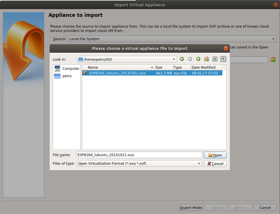
You can download the Espressif image from the following link ESP8266_GCC.zip.
After downloading, you need to import the Lubuntu Linux image into the Virtual Box. To do this, select the downloaded image from the File-> ImportAppliance menu item.


To make the Lubuntu Linux screen the same size as the open window, choose View-> Adjust Window Size from the Virtual Box menu.
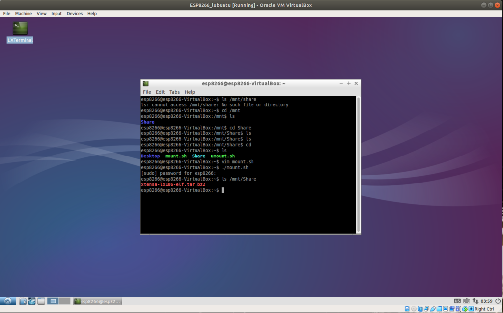
Now you need to copy the Toolchain. To do this, copy the archive xtensa-lx106-elf.tar.bz2 to a shared directory (I have $ HOME/VM/Share). In the running Lubuntu image, it will be mounted to /mnt/Share.
Lubuntu default username is ESP8266, espressif password.
Go to the home directory (cd) and run the mount.sh script to mount the shared directory
$ cd

$ ./mount.sh
You need to copy the toolchain to the home directory and extract it from the archive.
$ cp /mnt/Share/xtensa-lx106-elf.tar.bz2 ~

$ cd && tar -xf xtensa-lx106-elf.tar.bz2
Let’s check the installed compiler
$ xtensa-lx106-elf-gcc --version
Espressif offers to install its SDK in the Share directory, designed to share files between the virtual machine and the host machine. There are objective reasons for this. The size of the Lubuntu Linux image from Espressif is about 8GB, if you install all the SDKs in a virtual machine, you will very soon run out of free space on the Lubuntu disk.
Therefore, you have a choice – to install your own virtual machine (Lubuntu, Fedora, etc.) with a disk size of at least 20GB or use the Share directory to install all available SDKs.
Programming ESP8266 in ESP-Open-SDK
The ESP-Open-SDK provides software development tools for the ESP8266 and ESP8266EX chips.
To install the ESP-Open-SDK, you must first install additional packages, to do this, open lubuntu in the virtual machine and enter the commands:
$ sudo apt install make unrar-free autoconf automake libtool gcc g++ gperf \

flex bison texinfo gawk ncurses-dev libexpat-dev python3-dev python3 python3-serial python3-pip\

sed git unzip bash help2man wget bzip2
Install the esp-open-sdk package in the /opt directory
$ cd /opt

$ sudo git clone --recursive https://github.com/pfalcon/esp-open-sdk.git
Then you need to change the owner of the esp-open-sdk directory from root to esp8266
$ sudo chown -R esp8266:esp8266 /opt/esp-open-sdk

$ ls -l
Next, go to the directory esp-open-sdk and start the build process:
$ make STANDALONE=n
The build process is quite long in both native and guest Linux.
The toolkit will be installed in the /opt/esp-open-sdk/xtensa-lx106-elf directory
If you check the version of the compiler that has just been installed and copied from the ESP8266_GCC.zip archive, it turns out that esp-open-sdk contains a newer version of the toolkit.
Therefore we will register a new way to xtensa-lx106-elf toolkit in system variable PATH
$ cd

$ sudo vim .bashrc

export PATH=/opt/esp-open-sdk/xtensa-lx106-elf/bin:$PATH

$ source .bashrc
Let’s check the compiler version in the terminal window
$ xtensa-lx106-elf-gcc --version
Install the esptool utility for programming Flash memory of the ESP8266 module:
$ sudo pip3 install esptool
Now it’s time to add FreeRTOS support to our toolkit by running the following commands:
$ cd /opt

$ sudo git clone --recursive https://github.com/Superhouse/esp-open-rtos.git

$ sudo chown -R esp8266:esp8266 /opt/esp-open-rtos
To access the ESP8266 module to the WIFI network, you must specify its name (SSID) and password, to do this, create a header file private_ssid_config.h and prescribe the following parameters:
$ cd /opt/esp-open-rtos/include

$ vim private_ssid_config.h
|
1 2 |
#define WIFI_SSID "mywifissid" #define WIFI_PASS "my secret password" |
If you are running a guest Linux operating system, you need to activate your USB-UART converter in VirtualBox. To do this, simply select your converter in the menu Devices-> USB-> Your USB to UART Bridge Controller. But if the host system is also similar to Unix (Linux, MacOS), you must first add your user to the group of vboxusers:
$ sudo usermod -aG vboxusers $USER
Then connect the USB-UART adapter to the USB port and start the Virtual Box, select your converter in the menu Devices-> USB-> Your USB to UART Bridge Controller
Compile an example of the HTTP server and load the firmware into the ESP-12F module, not forgetting to set GPIO0 = 0:
$ cd /opt/esp-open-rtos/

$ make flash -j4 -C examples/http_server ESPPORT=/dev/ttyUSB0
After successful firmware of the module, turn off the power, set GPIO0 = 1 and re-power the ESP-12F module.
In the web browser window you can see the operation of the built-in HTTP server:

ESP8266 programming in SDK from Espressif
Espressif provides its proprietary SDK for programming modules based on ESP8266 , which actually consists of two independent parts: non-OS SDK and RTOS SDK.
Each of the provided SDKs contains sample programs.
Examples of non-OS SDKs have a program that demonstrates the expansion of the number of supported AT commands by adding custom ones.
The RTOS SDK is based on the FreeRTOS real-time operating system and contains many more examples than the non-OS SDK.
We can also compile examples from the SDK in a virtual machine, which is exactly why Espressif gave it to us.
Documentation for a quick start with the SDK can be downloaded from the manufacturer’s website ESP8266 SDK Getting Started Guide.
Install the RTOS SDK and non-OS SDK from Espressif in the guest OS lubuntu:
$ cd /opt

$ sudo git clone https://github.com/espressif/ESP8266_RTOS_SDK.git

$ sudo git clone https://github.com/espressif/ESP8266_NONOS_SDK.git

$ sudo chown -R esp8266:esp8266 /opt/ESP8266_RTOS_SDK

$ sudo chown -R esp8266:esp8266 /opt/ESP8266_NONOS_SDK
Let’s start with the most interesting, namely with examples of programs for RTOS SDK.
But first you need to install the RTOS SDK, to do this, run the following commands:
$ cd /opt/ESP8266_RTOS_SDK

$ ./install.sh

$ source ./export.sh
After installing the RTOS SDK, the compiler version will be even newer:
$ xtensa-lx106-elf-gcc --version

xtensa-lx106-elf-gcc (crosstool-NG esp-2020r3-49-gd5524c1) 8.4.0

Copyright (C) 2018 Free Software Foundation, Inc.

This is free software; see the source for copying conditions. There is NO

warranty; not even for MERCHANTABILITY or FITNESS FOR A PARTICULAR PURPOSE.
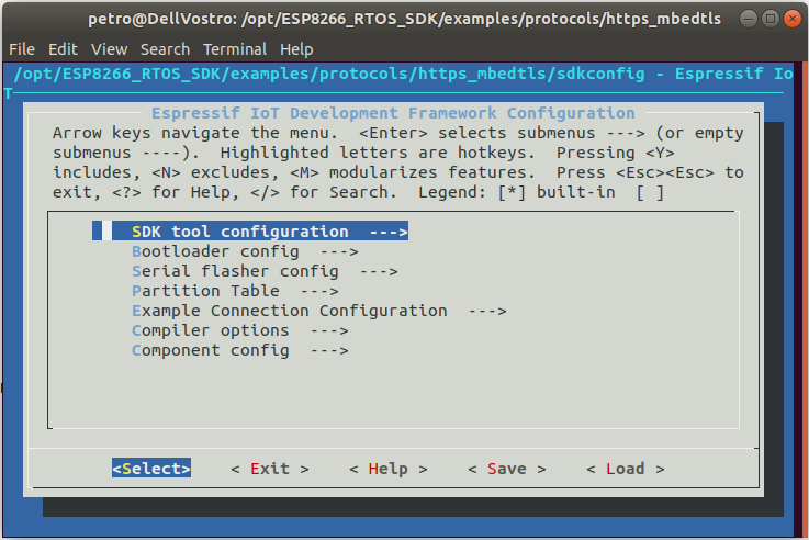
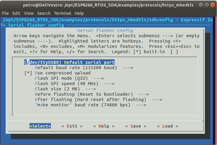
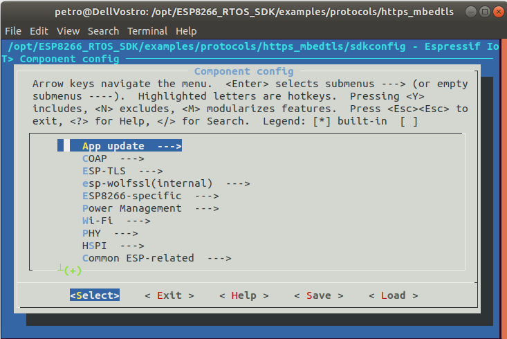
Compile an example of the https client built on the basis of the mbed TLS library for ESP8266:
$ cd /opt/ESP8266_RTOS_SDK/examples/protocols/https_mbedtls

$ make
The configuration menu is starting, configure the basic parameters as shown in the following pictures:


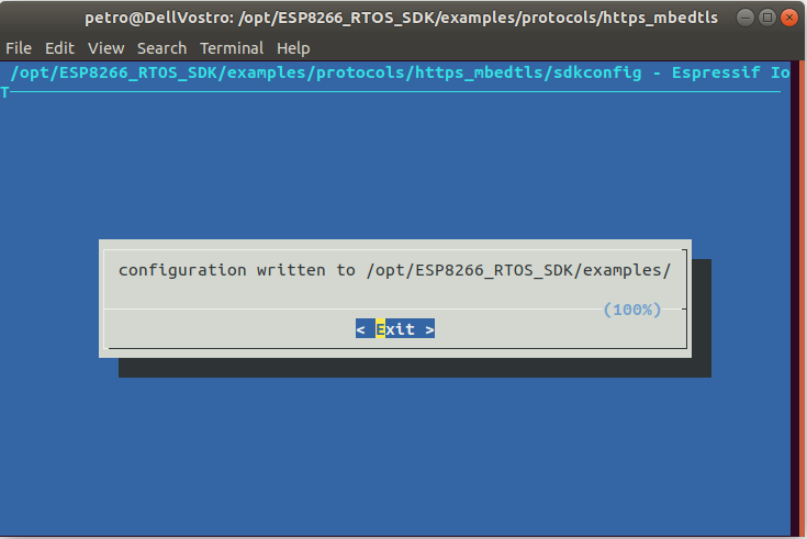
Upload the firmware to the module ESP-12F (do not forget about GPIO0 = 0) using the command:
$ make flash

Check the information displayed by the module by running the following command:
$ make monitor

To exit the PySerial-based monitor, press Ctrl +].
You can select the serial port baud rate when configuring the example, for this you can run the configuration again and set the required baud rate, the default baud rate is 74880 baud.
make menuconfig

If you decide to change the baud rate of the monitor, then do not forget to change the baud rate of data output in the UART.

It’s time to test the example for the non-OS SDK. Working with non-OS SDK has its own characteristics. In order to compile any example from the /opt/ESP8266_NONOS_SDK/examples/directory, you must copy the selected example to a higher level directory (to /opt/ESP8266_NONOS_SDK).
Compilation can be done in two ways: by calling the gen_mics.sh script and then entering the required parameters interactively, or passing the parameters to the command line along with make (actually gen_misc.sh does the same thing).
Let’s try to run an example of MQTT – the client on the ESP-12F module.
MQTT (Message Queue Telemetry Transport) is a network protocol running on top of TCP/IP that has a publisher-subscriber architecture. The protocol requires a running server, the so-called MQTT broker. MQTT clients exchange messages with each other through the MQTT broker. To do this, some customers (subscribers) sign up to receive messages from other customers (publishers), when one of the publishers sends a message, all subscribed customers immediately receive the sent message.
In order to test an example with ESP8266_NONOS_SDK/examples/esp_mqtt_proj you need to install MQTT broker. The most common MQTT broker for Linux is called Eclipse Mosquitto.
Installing MQTT broker Mosquitto on Raspberry Pi
Before installing Mosquitto, you need to update:
$ sudo apt-get update

$ sudo apt-get upgrade
Add a repository for downloading Mosquitto:
$ sudo wget http://repo.mosquitto.org/debian/mosquitto-repo.gpg.key

$ sudo apt-key add mosquitto-repo.gpg.key

$ rm -f mosquitto-repo.gpg.key

$ cd /etc/apt/sources.list.d/

$ sudo wget http://repo.mosquitto.org/debian/mosquitto-stretch.list

$ sudo apt-get update
Install Mosquitto
$ sudo apt-get install -y mosquitto mosquitto-clients
Launch Mosquitto
$ sudo service mosquitto restart
Now you need to test the work of subscribers and publishers.
To do this, first subscribe, open a new terminal window and enter:
$ mosquitto_sub -d -t /mqtt/topic/0
Open another window of the terminal and publish the message with the command:
$ mosquitto_pub -d -t /mqtt/topic/0 -m “Hello world!”
The message “Hello world!” should appear in the subscriber window.
In a previous post, I described how to set a static IP address for a server on a Raspberry Pi 3. The IP address of the board can be determined using the command:
$ hostname -I
MQTT client example using ESP8266 non-OS SDK
First, copy the example esp_mqtt_proj to the root directory ESP8266_NONOS_SDK:
$ cp -R /opt/ESP8266_NONOS_SDK/examples/esp_mqtt_proj /opt/ESP8266_NONOS_SDK

$ cd /opt/ESP8266_NONOS_SDK/esp_mqtt_proj
The IP address of the broker running on the Raspberry Pi MQTT and a few more parameters must be added to the header file mqtt_config.h:
$ vim include/mqtt_config.h
|
1 2 3 4 |
#define MQTT_HOST “IP address of MQTT broker” #define MQTT_PORT 1883 #define STA_SSID “Your SSID” #define STA_PASS “Your password” |
Run the script gen_mics.sh to build the project, in the process of the script you need to enter several parameters, as shown in the following picture:


Next, the compilation should start, but if this does not happen and you see an error message, you need to change the default Python interpreter to the old version of Python 2.7.
ESP8266_NONOS_SDK uses an outdated version of Python, Espressif is not going to support this version of the SDK anymore, but recommends using ESP8266_RTOS_SDK instead.
$ python --version

Python 3.6.9

$ which python

/usr/bin/python

$ sudo rm /usr/bin/python

$ sudo ln -s /usr/bin/python2.7 /usr/bin/python

$ python --version

Python 2.7.17
The second method of compilation:
$ make COMPILE=gcc BOOT=new APP=1 SPI_SPEED=40 SPI_MODE=QIO SPI_SIZE_MAP=4
To firmware the ESP-12F module, as usual, connect GPIO0 to the ground and enter the following commands:
$ cd ../bin

$ esptool.py erase_flash

$ esptool.py --port /dev/ttyUSB0 write_flash --flash_mode qio --flash_size 32m --flash_freq 40m 0x0000 boot_v1.7.bin 0x1000 upgrade/user1.4096.new.4.bin 0x3FB000 blank.bin 0x3FC000 esp_init_data_default_v08.bin 0x3FE000 blank.bin

A memory map for storing code and settings in SPI Flash is described in the ESP8266 SDK Getting Started Guide documentation.
Let’s check an example, for this purpose we open on Raspberry Pi three terminals then we subscribe in each of them on reception of messages from the MQTT client:
$ mosquitto_sub -d -t /mqtt/topic/0

$ mosquitto_sub -d -t /mqtt/topic/1

$ mosquitto_sub -d -t /mqtt/topic/2
You can also check the reverse effect such as publish messages in topics 0 – 2.
To do this, in one terminal window you can enter commands in turn:
$ mosquitto_pub -d -t /mqtt/topic/0 -m “Hello ESP8266 /0”

$ mosquitto_pub -d -t /mqtt/topic/1 -m “Hello ESP8266 /1”

$ mosquitto_pub -d -t /mqtt/topic/2 -m “Hello ESP8266 /2”
That’s all, I wish you successful experiments with modules based on ESP8266!
Viewed 66251 times by 10878 viewers
Comments